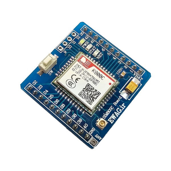
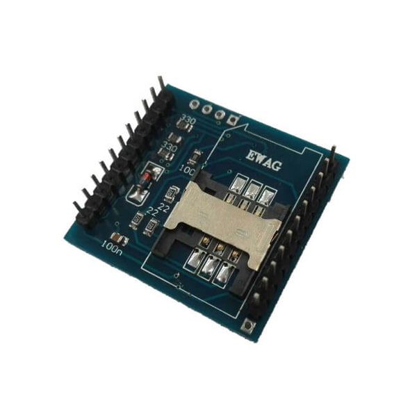
هدربرد (برد راه انداز) میکروکنترلرهای CORTEX M3 با امکانات اولیه جهت کار با میکروکنترلرهای LPC1768 شرکت فیلیپس. با توجه به 100 پایه بودن میکرو، دو ردیف پین هدر در اطراف برد قرار گرفته که بر روی 2 بردبرد چسبیده به هم قابل قرارگیری است. از دیگر مزایای این برد راه انداز، تأمین ولتاژ مورد نیاز میکرو از طریق پورت USB به همراه کلید قطع وصل می باشد . یکی از امکانات ویژه این برد قابلیت پروگرام نمودن میکرو از طریق پورت USB می باشد. در این روش شما هیچ احتیاجی به سخت افزار خاصی نداشته و فقط از طریق وصل نمودن کابل USB به رایانه می توانید میکروکنترلر را پروگرام نمایید. جهت پروگرام کردن این میکرو می توانید از 2 طریق ارتباط پورتUSB و یا پورت JTAG اقدام نمایید .

| 01 | حداقل مدار جهت راه اندازی میکروکنترولر LPC1768 |
| 02 | بدون نیاز به پروگرامر مجهز به بوت لودرUSB |
| 03 | دارای خروجی تمام پایه های ورودی خروجی به ترتیب شمارشی |
| 04 | داراي کانکتور full speed USB 2.0 |
| 05 | امکان نصب مستقیم برد بر روی بردبرد |
| 06 | دارای خروجی ولتاژهای 3.3 و 5 ولت |
| 07 | دارای کلید قطع و وصل تغذیه |
| 08 | امکان فعال و غیر فعال کردن پورت های تمامی امکانات جانبی میکرو، از قبیل USB ، JTAG ، DEBUG ، VREF و … |
| 09 | داری خروجی کانکتور JTAG استاندارد |
| 10 | دارای دکمه RESET |
| 11 | کریستال 32.768KHZ برای راه اندازی RTC داخلی |
| 12 | کریستال 12 مگاهرتز برای راه اندازی میکرو کنترلر |

General description :
The LPC1768 are ARM Cortex-M3 based microcontrollers for embedded applications featuring a high level of integration and low power consumption. The ARM Cortex-M3 is a next generation core that offers system enhancements such as enhanced debug features and a higher level of support block integration.
The LPC1768 operate at CPU frequencies of up to 100 MHz. The ARM Cortex-M3 CPU incorporates a 3-stage pipeline and uses a Harvard architecture with separate local instruction and data buses as well as a third bus for peripherals. The ARM Cortex-M3 CPU also includes an internal prefetch unit that supports speculative branching.
The peripheral complement of the LPC1768 includes up to 512 kB of flash memory, up to 64 kB of data memory, Ethernet MAC, USB Device/Host/OTG interface, 8-channel general purpose DMA controller, 4 UARTs, 2 CAN channels, 2 SSP controllers, SPI interface, 3 I2C-bus interfaces, 2-input plus 2-output I2S-bus interface, 8-channel 12-bit ADC, 10-bit DAC, motor control PWM, Quadrature Encoder interface, four general purpose timers, 6-output general purpose PWM, ultra-low power Real-Time Clock (RTC) with separate battery supply, and up to 70 general purpose I/O pins.
Features and benefits
♦ARM Cortex-M3 processor, running at frequencies of up to 100 MHz (LPC1768. A Memory Protection Unit (MPU) supporting eight regions is included.
♦ARM Cortex-M3 built-in Nested Vectored Interrupt Controller (NVIC).
♦Up to 512 kB on-chip flash programming memory. Enhanced flash memory accelerator enables high-speed 120 MHz operation with zero wait states.
♦ In-System Programming (ISP) and In-Application Programming (IAP) via on-chip bootloader software.
♦ On-chip SRAM includes:
♦ 32/16 kB of SRAM on the CPU with local code/data bus for high-performance CPU access.
Two/one 16 kB SRAM blocks with separate access paths for higher throughput.
These SRAM blocks may be used for Ethernet, USB, and DMA memory, as well as for general purpose CPU instruction and data storage.
♦ Eight channel General Purpose DMA controller (GPDMA) on the AHB multilayer matrix that can be used with SSP, I2S-bus, UART, Analog-to-Digital and Digital-to-Analog converter peripherals, timer match signals, and for memory-to-memory transfers.
♦ Multilayer AHB matrix interconnect provides a separate bus for each AHB master.
AHB masters include the CPU, General Purpose DMA controller, Ethernet MAC, and the USB interface. This interconnect provides communication with no arbitration delays.
♦ Split APB bus allows high throughput with few stalls between the CPU and DMA.
♦ Serial interfaces:
♦ Ethernet MAC with RMII interface and dedicated DMA controller. (Not available on all parts, see Table 2.)
♦ USB 2.0 full-speed device/Host/OTG controller with dedicated DMA controller and on-chip PHY for device, Host, and OTG functions. (Not available on all parts, see Table 2.)
♦ Four UARTs with fractional baud rate generation, internal FIFO, and DMA support.
One UART has modem control I/O and RS-485/EIA-485 support, and one UART has IrDA support.
♦ CAN 2.0B controller with two channels. (Not available on all parts, see Table 2.)
♦ SPI controller with synchronous, serial, full duplex communication and programmable data length.
♦ Two SSP controllers with FIFO and multi-protocol capabilities. The SSP interfaces can be used with the GPDMA controller.
♦ Three enhanced I2C bus interfaces, one with an open-drain output supporting full I2C specification and Fast mode plus with data rates of 1 Mbit/s, two with standard port pins. Enhancements include multiple address recognition and monitor mode.
♦ I2S (Inter-IC Sound) interface for digital audio input or output, with fractional rate control. The I2S-bus interface can be used with the GPDMA. The I2S-bus interface supports 3-wire and 4-wire data transmit and receive as well as master clock input/output. (Not available on all parts, see Table 2.)
♦ Other peripherals:
♦ 70 (100 pin package) General Purpose I/O (GPIO) pins with configurable pull-up/down resistors. All GPIOs support a new, configurable open-drain operating mode. The GPIO block is accessed through the AHB multilayer bus for fast access and located in memory such that it supports Cortex-M3 bit banding and use by the General Purpose DMA Controller.
♦ 12-bit Analog-to-Digital Converter (ADC) with input multiplexing among eight pins, conversion rates up to 200 kHz, and multiple result registers. The 12-bit ADC can be used with the GPDMA controller.
♦ 10-bit Digital-to-Analog Converter (DAC) with dedicated conversion timer and DMA support. (Not available on all parts, see Table 2)
♦ Four general purpose timers/counters, with a total of eight capture inputs and ten compare outputs. Each timer block has an external count input. Specific timer events can be selected to generate DMA requests.
♦ One motor control PWM with support for three-phase motor control.
♦ Quadrature encoder interface that can monitor one external quadrature encoder.
♦ One standard PWM/timer block with external count input.
♦ RTC with a separate power domain and dedicated RTC oscillator. The RTC block includes 20 bytes of battery-powered backup registers.
♦ WatchDog Timer (WDT). The WDT can be clocked from the internal RC oscillator, the RTC oscillator, or the APB clock.
♦ ARM Cortex-M3 system tick timer, including an external clock input option.
♦ Repetitive interrupt timer provides programmable and repeating timed interrupts.
♦ Each peripheral has its own clock divider for further power savings.
♦ Standard JTAG test/debug interface for compatibility with existing tools. Serial Wire Debug and Serial Wire Trace Port options.
♦ Emulation trace module enables non-intrusive, high-speed real-time tracing of instruction execution.
♦ Integrated PMU (Power Management Unit) automatically adjusts internal regulators to minimize power consumption during Sleep, Deep sleep, Power-down, and Deep power-down modes.
♦ Four reduced power modes: Sleep, Deep-sleep, Power-down, and Deep power-down. ♦ Single 3.3 V power supply (2.4 V to 3.6 V).
♦ Four external interrupt inputs configurable as edge/level sensitive. All pins on Port 0 and Port 2 can be used as edge sensitive interrupt sources.
♦ Non-maskable Interrupt (NMI) input.
♦ Clock output function that can reflect the main oscillator clock, IRC clock, RTC clock, CPU clock, and the USB clock.
♦ The Wake-up Interrupt Controller (WIC) allows the CPU to automatically wake up from any priority interrupt that can occur while the clocks are stopped in deep sleep, Power-down, and Deep power-down modes.
♦ Processor wake-up from Power-down mode via any interrupt able to operate during Power-down mode (includes external interrupts, RTC interrupt, USB activity, Ethernet wake-up interrupt, CAN bus activity, Port 0/2 pin interrupt, and NMI).
♦ Brownout detect with separate threshold for interrupt and forced reset.
♦ Power-On Reset (POR).
♦ Crystal oscillator with an operating range of 1 MHz to 25 MHz.
♦ 4 MHz internal RC oscillator trimmed to 1 % accuracy that can optionally be used as a system clock.
♦ PLL allows CPU operation up to the maximum CPU rate without the need for a high-frequency crystal. May be run from the main oscillator, the internal RC oscillator, or the RTC oscillator.
♦ USB PLL for added flexibility.
♦ Code Read Protection (CRP) with different security levels.
♦ Unique device serial number for identification purposes.
♦ Available as 100-pin LQFP (14 mm × 14 mm × 1.4 mm) and TFBGA1 (9 mm × 9 mm × 0.7 mm) package.

نحوه ی پروگرام کردن توسط بوت لودر هدر برد:
دیپ سوئیچ USBOT و USB را وصل کرده و پورت USB را متصل نمائید. با وصل کردن سوئیچ ON/OFF کامپیوتر باید برد را به صورت یک فلش درایو شناسایی کند. برای شناسایی برد نیازی به درایور ندارید.
با توجه به اینکه برنامه بوت لودر تا آدرس 0x1FFF حافظه کد میکرو را اشغال کرده است ، برنامه هایی که قصد پروگرام آن را دارید باید از آدرس 0x2000 شروع شوند. فایل HEX برنامه را توسط مبدل H-Convertor به فایل BIN تبدیل کنید. درایو شناخته شده را باز کرده و فایل موجود را پاک نموده و با فایل BIN تولیدی جایگزین نمایید.
دیپ سوئیچ SBOT را قطع کرده و مدار را خاموش، روشن نمایید. لازم به ذکر است که با یک بار خاموش و روشن کردن برد، فایل بوت لودر با همان نام اولیه نشان داده می شود و امری طبیعی می باشد.
پورت Jtag: برای استفاده از پورت جیتگ، کافیست کابل پروگرامر خود را به پورت جیتگ متصل نموده و فقط دیپ سویچ jtag را on نمایید.
کاربرد دیپ سوئیچ ها :
JTAG : برای فعال کردن پورت JTAG
USB : برای فعال کردن پورت USB
VREF : برای اتصال پایه VREF به VCC
SPBOT : برای فعال کردن بوت لودر سریال توسط نرم افزار Flash Magic
USBOT : برای فعال کردن بوت لودر USB
DEBUG : برای فعال کردن حالت عیب یابی توسط JTAG